Tufting Controls — TC3000 Model 7

Computerized control systems for carpet and rug tufting machines. Sold worldwide since 1986, with full downward compatibility for operators and pattern files.

1986 Tufting controls launched
13+ Machine types supported
200+ Control systems installed*

Built for the mill floor

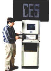
Here Bill Otto is shown with the portable keyboard/display terminal that has been used in all 200 previous control systems installed over the past years. All new systems are downward compatible both from use and functionality of this terminal.

The terminal is connected to the computer via a long cable so its position can be in close proximity of a fixer (running diagnostic programs), as well as the operator at the machine.

These same functions and displays are operational via the computer keyboard and color monitor, with obvious additional features available with the color monitor — displaying additional information and patterns, for example.

As mentioned, the portable keyboard/display functions are the same as older models, but also old pattern (diskette) files; older patterns will run on the newer control systems. The portable terminal functions are also operational via the computer keyboard and monitor.

Bill Otto with CES portable keyboard/display terminal for Model 7 tufting control
Portable keyboard/display terminal — used across hundreds of CES installations

At a glance

PlatformModel 7 / TC3000
HistoryWorldwide sales since 1986
Installations200+ control systems*
Cabinet size66″ H × 24″ W × 24″ D (typical)
Machine types13+ supported
Driver card64 LV/LC or 32 HV/HC fused outputs
Outputs / rackUp to 1,280 (20 × 64)
Outputs / cabinetUp to 5,120 (4 racks)
CardsIndustry-standard Euro Cards

*As described on the original CES tufting product page.

Inside the Model 7 cabinet

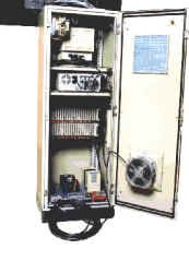
From the rear of the cabinet, the back of the monitor is shown at the top, then the computer, then the interface card rack — cables can be seen at the top of the cabinet. These connect the circuits in the interface card rack to the solenoids on the machine.

Some systems have a servo system under the interface card rack (not shown here) that controls a servo motor on the machine. The servo system operates in sync with the rug pattern such that the backing is advanced in fixed steps.

The backing motion begins on the needle upstroke when the needles clear the backing, with motion completion before the needles reenter the backing on the downstroke. The step distance is part of the pattern, and determines the stitch count, as well as eliminating backing motion when the needles are in the fabric.

In the bottom are power filtering, isolation, and regulating components. The coil of cables at the bottom connect to position sensors on the machine. An air system can be seen on the rear door.

Rear view of CES Model 7 control cabinet showing monitor, computer, and interface card rack
Rear of cabinet — monitor, computer, interface card rack, and machine cabling

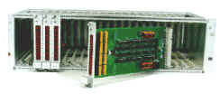
Euro-card racks and high-density I/O

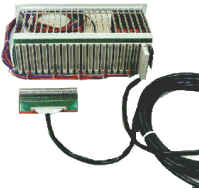
Industry-standard Euro Cards and racks are used. Each rack holds up to 20 solenoid interface PC boards, with 64 output circuits per board — 1,280 output signals per rack. The cabinet can hold 4 racks (extensions can be added) for a total per cabinet of 5,120 control outputs. CES has quoted systems with over 14,000 outputs.

The (coiled) ribbon cable shown is connected to the back of the card rack and has a machine wiring interface at the other end, depending upon the application. In this case, there is a solenoid interface PC board with a terminal strip to which machine solenoid wires are terminated.

The solenoid interface PC board connector pins come through the card rack backplane and the ribbon cable connects directly to the solenoid interface PC board connector, thus reducing the number of connections and in turn enhancing connection reliability.

  • Any PC board plugs into any slot in the rack
  • On-board power supply (regulator/rectifier) for board and solenoid power
  • Eliminates two large shared supplies that could take out the entire system
  • Programmable control PC board configures each rack to the machine

Some machines have multiple controls per yarn end, such as high/low plus cut/uncut. Two control outputs are needed per yarn end, and these outputs can be mapped on the programmable control board.

True status LEDs and board-level protection

True current indication

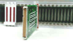
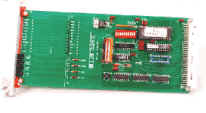
The front of the solenoid interface PC board has 64 red LEDs in series with 64 corresponding solenoids, and only illuminate when each corresponding solenoid is drawing current. Hence, the LED is a true indication of computer, circuit, and machine wiring integrity — the system “dances in lights” while running the machine or built-in diagnostics.
Board-level fusing

The solenoid output circuits are fused on the PC board so as to protect against both solenoid and machine wiring faults; fuses plug into pin sockets for easy replacement. Fusing other than on the PC board may not give complete protection.

Identification & viewing

On the PC board end plate is a number next to each LED for identification. The illumination pattern of all PC boards is seen through a smoked glass front panel.

Distributed power

Each PC board has an on-board power supply for both the PC board power and solenoid power, so as to eliminate the need for two large power supplies that could take out the entire system.

Machine types & pattern support

DesignTuft and control software support a broad set of industrial machine families. Older pattern files remain usable on newer Model 7 systems.

UTPA ICN ICN2 SCROLL2 SCROLL3 SCROLL3S HLCS LCL LCL2 FRS FRS2 COLORTEC TWEAVER YARNFEED1

DesignTuft pattern software Request upgrade info

Control software screen shots

Help screens and operator menus from the CES tufting control system — as published on the original Screen Shots page. Click a thumbnail to view it large, or click the main image to open full size.

Main menu

Call for upgrade information on existing software that includes help screens for simpler operation.

In production

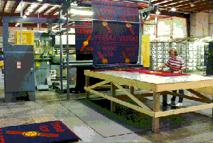
This picture shows floor mats coming off a production Colortec machine controlled by a Model 7 CES controller.

With both a remote handheld operator terminal and a built-in color monitor / keyboard, the machine operator can select patterns, change and display operating characteristics, run diagnostics, and do many other functions from two different locations around the machine.

Linked to CES pattern design software (including DesignTuft) and just about any Windows paint or drawing program, Model 7 systems put design ideas into carpet and rugs quickly and easily.

Explore DesignTuft Contact CES

Floor mats coming off a Colortec tufting machine controlled by CES Model 7
Colortec production — Model 7 CES controller

Specify a new control or upgrade an existing line

Call (706) 882-4704 for machine-specific quotes, harness kits, software upgrades, and demos.

Contact engineering Call (706) 882-4704